Автор: Pavlenko A.M., Koshlak H.V., Usenko B.O.
Категории:
thermal technology
The article suggests physical and mathematical models used in the design of vortex evaporation chambers for separating multicomponent media.
Key words: vortex, heat and mass transfer, model calculation.
Dr. sci, professor Anatoliy Pavlenko
Ph.D., associate professor Hanna Koshlak

Postgraduate Bohdan Usenko
Poltava National Technical Yuri Kondratyuk University, Poltava
P - pressure, Pa; W - circumferential component of the velocity, m/s; a - fluid tube; I - enthalpy; S -entropy; V - velocity phase, m/s; T - temperature, K; ρ - density, kg/m3; r - radius, m; z - coordinate axis of the vortex chamber, m; Mx - Maxa Number; V - the radial velocity component, m; γ(r) - mass removal rate, presented as a series with coefficients A1, A2, and the exponent a; B - hydrodynamic characteristics of the devices, K-the adiabatic index; U - axial component of velocity, m / s.
Introduction
For the design of vortex evaporation chambers extensive theoretical and experimental researches of aerodynamics of swirling flow in respect with changing in the volume and mass of the setting are required. The basis of investigation should provide a model of liquid flow in the vortex chamber [1] and analyze the possibility of using these results to describe the boiling of vortex flows.
The studies [2] indicate that the relative rotational speed with an increase in temperature (burning oil) in 1.5times increase relative to the speed of the cold flow. Axial velocity increased in 4 times. Relative values of total and static pressures for the heated chamber are higher than for the cold one. At the same time, the qualitative picture of the chamber remained without significant changes.
Let us consider first the physical representation of the process of the vortex flow boiling liquid, thus will be based on a physical model "cold" flow, presented in work [3].
1. Statement of the Problem
Figure 1 shows the diagram flashing flow. Due to the interaction along the boundaries a1, a2, a3 for cocurrent flow portion due to abrupt speed change section a1, a3 stream breaks up into vortex bundles, elongated along the surfaces parallel to the axis of flow. Vortex model of turbulent mixing layer is also discussed in detail in this work [4]. The resulting structure begins to move under the action of radial pressure drop.
In general, boiling in the flow occurs when the local pressure becomes lower than saturation value at the corresponding saturation temperature. If the device provides a global reduction in pressure, the liquid evaporates completely. When analyzing the results of research [5], a multi-stage model of superheated liquid boiling is traditionally adopted. In the first stage vapor bubbles are generated,

Figure 1: a - settlement scheme (the shaded area two-phase flow)
confluenting then into the flow tubes, which are accelerated to a greater extent than the main stream. The more the pressure gradient, the more clearly appear these stages of boiling up. The proposed model describes boiling up flow without reversibility. Application of this approach to the flow without gradient, could idealize this decision. But as vortex motion possible with significant pressure gradient, the assumption of irreversibility is justified and does not contradict the model of hydrodynamic and thermodynamic laws. Thus, referring to the figure 1, there are three areas of single-phase and two-phase flows. When the pressure drops to Pn the steam is generated, which flows in the form of separate tubes without friction heat exchange and stirring. By increasing the volume of the medium and lower density the speed leap is obvious. Tubes of current are characterized by isentropic flow.
The temperature and velocity in section tubes are not changed. With a further drop in pressure new tubes of current steam are created, the amount of liquid decreases. In the case of enough amount of overheating, the liquid evaporates completely. The non-evaporated portion of liquid is distributed in the tube of current in the form of droplets, and moves with the same speed as the steam. Evaporation process inside the vortex is conveniently represented on I-S diagram (Figure 2).
Using the basic thermodynamic relations, we can write an equality which follows from the diagram:
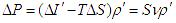
This equation is taken as the basis for further development of the model of evaporation and also fully characterizes presented physical model of flashing flow: boiling liquid formed cylindrical zone of vaporization, in which the saturation by vapor increases at approximation to the radius of the vortex while the pressure drops.
Evaporation rate and the final pressure value is determined by the level of overheating, on the hypothesis that the size of outlet opening corresponds to the mass flow of the setting. Following a reduced representation of flow phases, their speeds are different inside the vortex flow [8]. Let us assume that an increase of vapor content the phase velocities are approaching in their values and are aligned in the nozzle [9].

Figure 2 Representation process of boiling up I-S - diagram
2.Numerical simulation
The proposed above physical model of boiling process of superheated liquid in vortex devices can be represented by the following system of equations for the main area of the vortex:
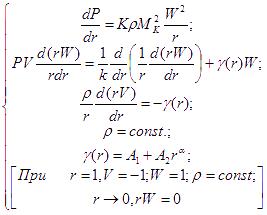 (2)
(2)
Flows in areas of vortex flow can be represented by the following mathematical model:
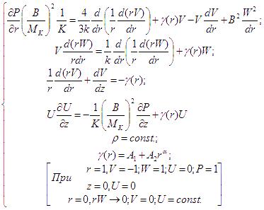 (3)
(3)
Figure 3 shows the combined solution of (2) and (3) for flashing and "cold" flows. Graphic dependences illustrate the proposed physical representation of the process of liquid boiling in the vortex and are consistent with experimental data of this work[3]. These mathematical models can be at the core of calculation and design of vortex contact apparatus, or vortex devices in which the mass flow is variable, for example, devices for thermal separation of emulsions [6]. Considering the experience of exploitation of such devices, it should be noted that, as a rule, a vortex flow in the evaporation process is almost completed. Therefore, in many cases g( r)=0 can be taken without substantial error calculation in the system of equations (3).


Figure 3 - The solution of equations (2) and (3)
Solution of the equations can be written as:
 (4)
(4)
 (5)
(5)
Let us make calculations if 
 (6)
(6)
We form, nonlinear right side of the first equation.
Desired equation to calculate the pressure field can be represented in the form of:
 (7)
(7)
where:

4. Discussion of results
From the graph in Figure 3, which reflects the dependence of medium pressure on the radius of vortex follows that the qualitative characteristics of this function remain unchanged when heated. However, in case of reaching the saturation temperature, pressure field deforms substantially up to keeping a constant value, which is almost equal to the inlet pressure. Such critical modes of the device operation should be assessed on the stage of forecasting of working structural and technological parameters.
The graphs of Figure 3 also reflect a change in the flow rate in the case of phase transition, i.e. increase or reduction of medium volume in the vortex layer.
Calculated dependences are in satisfactory agreement with the experimental data obtained in a vortex device, through which superheated water relatively by normal conditions was passed.
5. Conclusion
To determine the quantitative characteristics of the process, it is necessary to know the mass flow rate (mass removal) g(r) and also to clarify the pole slipping coefficient value.
From the represented data follows that the change of vortex flow weight at EFV boiling in the vortex evaporator (during combustion, condensation, etc.) leads to deformation of pressure fields and velocity components. This feature should be considered when designing of appropriate devices.
References
1. A.M. Pavlenko, Stability of emulsions in technological influences. Dnepropetrovsk, Science and Education, 2000, P.140
2. Dolinskiy A.A., A.M. Pavlenko, B.I. Basok Thermophysical processes in the emulsions. Kiev, Naukova Dumka, 2005. P.268.
3. Pavlenko A.M., Basok B.I. Integration emulsions in vortex devices. DGTU, Dnepropetrovsk, 2009. P.247
4. Pavlenko A.M., Basok B.I, Avramenko A.A. Heat Conduction of a Multi-Layer Disperse Particle of Emulsion. Heat Transfer Research, 2005, Vol.36, Nos.1&27, P.55-61.
5. Shlikhting G. Boundary-layer theory. Moscow, Science, 1974. P.711
6. Deych M.E.Technical gas dynamics. Moscow, Energy, 1974. P.592
7. Lyakhovsky D.N. Questions aerodynamics and heat transfer in the boiler furnace processes. Gosenergoizdat, 1958. P.97.
8. Pavlenko A.M., Usenko B.O., Koshlak A.V. (2014). Analysis of thermal peculiarities of alloying with special properties. Metallurgical and Mining Industry, No2, pp. 15-19.
9. Koshlak A.V., Pavlenko A.M., Usenko B.O.(2014). Thermal conductivity of the gas in small space. Metallurgical and Mining Industry, No2, pp. 20-24.