Design and Fabrication of a Four-piece Channel Type ESR Mould of Mild Steel |
\\ Статьи
Design and Fabrication of a Four-piece Channel Type ESR Mould of Mild Steel
ESR mould design and construction are constantly under review and development to cater the demands of a wide range of shapes and cross section of ingots to be produced by the ESR process. In the present study, initially four-piece channel type split-mould of mild steel was designed and fabricated for production of ESR ingots of rectangular cross-section 78 × 68 mm and around 350 mm height. The initial design developed a problem of localized over-heating at the bottom of the mould resulting in welding with the solidified ESR ingot. The problem was studied through a Perspex model of the broad face of the mould. Based on this study the mould was redesigned. The redesigned mould performed satisfactorily and used for production of ESR ingots of larger sizes.
Keywords: ESR, water jacketed split mould, over-heating, perspex model

T. R. Bandyopadhyay
Ex-faculty of Metallurgical Engineering,
National Institute of Technology, Durgapur-713209,
West Bengal, India and presently ‘Visiting Faculty’
in Biju Patnaik National Steel Institute, Odisha,India
Introduction
The electroslag remelting is a consumable electrode remelting process in which the metal in the form of a bar or rod, which is the consumable electrode, is melted under a layer of molten slag which is super heated by the passage of electric current. The slag used has specific electrical resistivity of the order of 0.002 – 0.008 ohm-m and provides heat due to resistance heating [1]. The tip of consumable electrode, which is kept immersed in the molten slag, melts due to high temperature of slag bath. The droplets of molten metal fall through the slag bath and join the metal pool below it. The metal pool progressively solidifies in a water-cooled mould resulting in the formation of ESR ingot. As the process continues and the growing ingot displaces the slag bath in an upward direction, the molten metal pool and the ingot below it are enveloped by the solidified slag skin. On stripping the ingot from the mould, the solid slag shell flakes off and leaves behind a smooth and shiny ingot surface.
Mould for Electroslag Remelting (ESR) has to perform multifarious functions: it holds the liquid slag bath which provides heat due to passage of current through it, contains the molten metal as it accumulates and imparts the required shape to the solidified metal. Apart from these, the mould is also required to transfer a major portion of the heat generated in the process through its wall to the cooling water and also, to conduct a substantial current during the process. Efficient mould design and fabrication, therefore, has a considerable bearing on the production of ingots through ESR
The main criteria for the selection of the material for mould fabrication are good thermal conductivity and ability to withstand the thermal shock. Copper is the favourite choice for the mould material because of its high thermal and electrical conductivity. As a result copper can be used for fabrication of mould up to a section thickness of around 20 mm [1]. But the main disadvantage with copper is its cost. Moreover, it has been found that mild steel moulds, for short runs e.g. 50-60 heats, are more economical than copper moulds because of noticeable lower cost, high adaptability to manufacture and ease of repair 1.
In the present investigation four–piece rectangular channel type mould of smaller dimension was initially fabricated from mild steel, tested and subsequently larger moulds were fabricated to carry out ESR melts.
Experimental
Four mild steel channels, two channels each of 450 mm high, 150 mm width and 7.5 mm thickness and the other two each of 450 mm, 75 mm width height and 7.5 mm were selected for fabrication of the four–piece rectangular channel type mould. Both the inner and specially the outer surface which will form the mould face of each of the channel was ground and cleaned.
Back side of each of the channel was welded with a back up plate of 430 mm high and 6.5 mm thick with the help of spacer pins in order to keep a uniform gap of 5 mm throughout and also to form opening in the form of slit for inlet and outlet of water at the two ends of the channel. The slit at each end was covered by a distribution box for cooling water into the slit.
In the present investigation ESR ingots of 78 × 68 mm cross section and around 350 mm height were produced from 40 mm round electrodes in a water jacketed four-piece split-mould of mild steel (Fig. 1). Out of the four-piece split-mould, two–piece each is of 75 mm width and 450 mm height (narrow-face) and the other two–piece each is of 150 mm width and 450 mm height (broad-face). The cooling water entered through a pipe fitted at the bottom into a distribution box (pressure equalizer) that in turn fed the water into cooling channel of 5 mm gap through an opening. The cooling water outlet pipe was fitted at the top of the mould. During ESR, the current, voltage and average power input were maintained at 1300 A, 32 ± 2 V and 41 kW respectively.
Over-heated zone
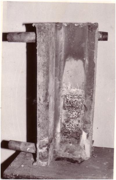
Figure 1 ESR mould showing 2 pieces forming half the mould
The value of heat flux in ESR mould is usually of the order of 1 MW m-2 which is far less than in continuous casting of the order of 2-2.5 MW m-2 1. This is because the ESR process is characterized by the formation of thin solidified slag skin of around 1-2 mm on the inside face of the mould which reduces heat transfer from the solidified ingot to the cooling water via mould. Accordingly, water flow velocity in the water-cooling channel is required to be 1.4 m s-1 1. In the present case the cooling water velocity was maintained at 1.08 m s-1 resulting in volumetric water flow rate of 40 L min-1.
Initially at the bottoms of the both broad and narrow–face mould a cut out was given with the view of obtaining a smoother flow of water into the cooling channel. But, in the initial melts moulds were getting overheated at a height of about 40 mm from the bottom (Fig. 1). As a result, the solidified ingot used to stick with the mould at that over-heated zone causing great difficulty in stripping of the solidified ingot. Therefore, a Perspex model of the broad face of the mould was made to visualize the effect of the shape and width of the cut out through which water entered into the cooling channel from the pressure equalizer, on the flow characteristics of the cooling water (Fig. 2).
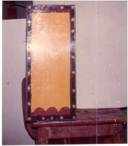
Figure 2 Perspex model of the broad face of the ESR mould
During the study of the model it was observed that the water entered the cooling channel right through the edge of the contour of the cut-out since this offered a less resistance path to the flow of water. This resulted in non-wetting of the space between the bottom of the mould and the edge of the contour causing entrapment of air bubbles. Eventually, the mould got over-heated in that zone. Based on this study two faces of the mould were redesigned by replacing the contour in the form of cut-out with an opening in the form of a slit of 10 mm for the entry of the cooling water in the channel. The new design of the mould is shown in Fig 3.
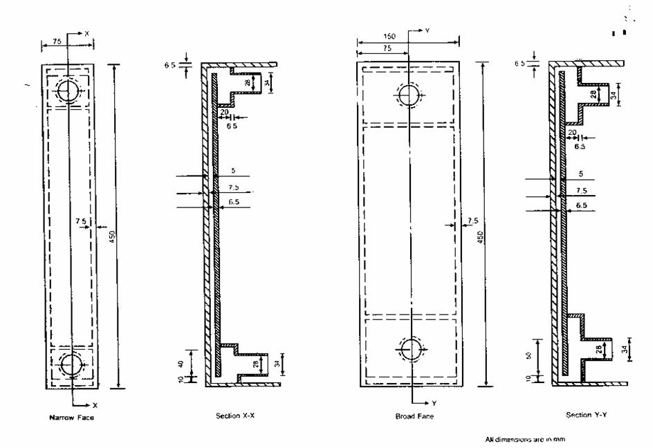
Figure 3 Two faces of the ESR mould
During the trial runs with the redesigned mould the current, voltage and average power input were maintained at 1300 A, 34 ± 2 V and 41 kW respectively during ESR of mild steel electrode. The difference in temperature between the outlet and inlet water during ESR was found to be 50C. The redesigned mould performed satisfactorily and ESR ingots were produced without any problem of sticking of the ESR ingot with the mould. An ESR ingot produced during the trial runs is shown in (Fig. 4). The average weight of the ESR ingots produced during the trial runs was 12 kg.
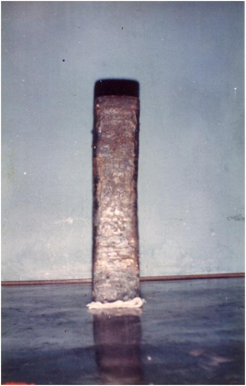
Figure 4 ESR ingot produced using redesigned mould in trial runs
After successful trials with the mould, the design was employed for fabrication four - piece mild steel channel mould for production of larger size ESR ingots (Fig. 5a and 5b). The ESR ingots produced were of various cross sections in the form square (500 x 150 x 150 mm) to slab (600 x 280 x 80 mm). The power input was in the range from 100 - 120 kW.
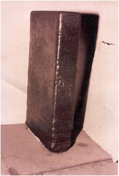
Figure 5a ESR slab produced by using produced by redesigned mould redesigned mould
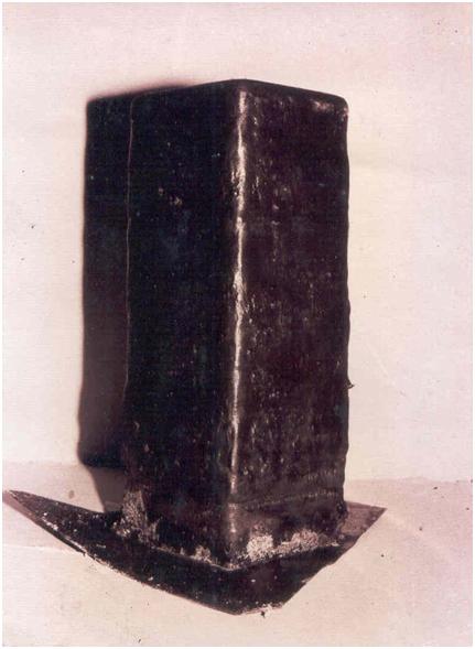
Figure 5b ESR ingot of square cross section produced by using redesigned mould
Due to formation of scaling due to passage of cooling water at the back wall of the each piece of the mould there is a possibility of narrowing down the gap. This can be prevented by passing HCl at typically 18% concentration periodically through the mould to remove rust or iron oxide scale.
Conclusion
The redesigned mould four-piece mild steel channel mould performed satisfactorily. ESR ingots of various cross-sections were produced without any problem of sticking of the ESR ingot with the mould surface. Split mould renders very convenient and easy way of stripping off the solidified ESR ingot
Reference
[1]. G. Hoyle: ‘Electroslag processes principles and practice’, 1983, 121-123, London and New York, Applied Science Publishers.

