Автор: Pavlenko A.M., Koshlak H.V., Usenko B.O.
Категории:
thermal technology
The gas hydrate technologies can be alternative to the traditional methods of the rational use of hydrocarbon gases. However the known constructions of apparatuses for the production of gas hydrates cannot fully satisfy the condition of their industrial use. Authors offer to carry out the high-quality contact of gas and water at formation of gas hydrate by jet apparatuses with a free falling jet. On their basis a technological chart for realization of continuous cycle of production of gas hydrate is offered. Method of production, the main technological parameters and principal scheme of the installation for the production of associated petroleum gas of hydrate are developed. Technology provides their production in the form suitable for transportation and long term storage without addition of cooling. The modular gas hydrate laboratory setting for testing elements of gas hydrate technology in oil and gas sector has been developed and created. Method of intensive hydrate formation and the device for contacting phases on the basis of jet system with free falling jet are developed. The mathematical model of the process is developed and empirical equation coefficients are determined. Parameters of continuous cycle of gas hydrates are substantiated.
Key words: gas hydrate, jet apparatus, free falling jet, continuous cycle of production, coagulation, heat of gas hydration.

Dr. sci, professor Anatoliy Pavlenko
Ph.D., associate professor Hanna Koshlak

Postgraduate Bohdan Usenko
Poltava National Technical Yuri Kondratyuk University, Poltava
1. Introduction
1.1. Problem definition and its relationship with important scientific and practical tasks.
In many cases, the traditional assembly technology, and use (consumption) much of the resources of hydrocarbon gases (associated petroleum, deposits, in-pit) are ineffective or economically unjustified. At the same time in recent years there happened rapid development of technology accumulation (storage), transportation and long term storage of hydrocarbon gases in hydrate form. However, widespread implementation due to insufficient testing of its elements has not yet acquired. The main problems that hinder the production of gas hydrates of natural gas, and hence the widespread introduction of gas hydrate technology is creating a closed cycle, withdrawal of gas hydrates formed, its maximum dehydration, maintaining the integrity of the formed hydrates. Plants for the production of semi hydrates, as applicable, and those that are under development, there are still quite underdeveloped in terms of energy consumption and optimizing industrial operations. The analysis of the structural features of known reactors showed that none of them, in our opinion, can fully meet the requirements of industrial applications.
1.2. Analysis of recent research and publications in which a solution of this problem
Equipment for the production of synthetic hydrates, different ways of creating contact between the liquid and gas: spray water into the gas phase (by spraying water into the gas fed through nozzles, conductors and sprayers), the introduction of gas into the liquid phase by bubbling or stirring method and combined input reagents.
During spraying water in gas at the stage of gas-water interconnection is hydrating. Its mechanism consists of the following steps [1]: 1) the embryo formed hydrates, 2) drop cover gas hydrate crust thickness 0.04 mm 3) crust thickens to 0.24 mm. The water in the hydrate capillaries rises to the gas phase. Since the fluid is compressed enough, the external gas pressure can break hydrated crust. Thus, hydrate enjoys the water.
During the bubbling gas to its liquid bubble covered hydration rind. As the gas is compressible, in this case appears "effect of eggs" [2]: crust under pressure breaks inside. Around formed crust particles have formed hydrate. So, with this method of hydrate water is much less taken.
The process of hydrate formation is to create a contact interface for dissolving gas in water at appropriate thermobaric conditions, the formation and growth of hydrate structures and allocate the appropriate amount of heat hydrate. Depending on how the contact phase in the gas hydrates can be a different, sometimes very large amount of water. And in the case of the captured water (water droplets covered with hydrate crust) it is difficult to remove or tie in gas hydrates. Capture by hydration structures of gas bubbles ultimately leads to improving the quality of the resulting product as bubbles covered hydrated crust, relatively easily broken, or there is a gradual diffusion of gas hydrate due to contact with free water and its binding. Therefore, for the production of gas hydrates with minimal water content appropriate to apply a way that provides for the introduction of gas in water volume. Bubbling gas into the bottom part of the reactor volume is being doing in such a way. However, the main problem of this method and the main direction of its improvement is to reduce the size of the bubbles to increase contact area phases, as well as extending the time of the bubbles in the liquid.
2. Result and discussion
2.1. Excretion of the unsolved earlier aspects of the problem which the article is dedicated
Depending on how the supply of energy to the working environment in order to create a contact phase contact apparatus for gas hydrate formation, similar to the absorptive devices can be divided into units of energy supply gas phase, liquid phase, mechanical agitators and their combinations.
A characteristic feature of the apparatus of power supply liquid and gas phase is the presence or mechanical or hydrodynamic mixing device. The most widely used devices with mechanical mixers that are installed, usually over gas distribution device. The main disadvantage of apparatus with mechanical mixing devices are unreliable operation of these devices.
2.2. Article purposes formation
The aim is to develop technical solutions and process parameters of continuous production of gas hydrates, which would satisfy the requirements of industrial application.
2.3. Presentation of the main material
The study of the mechanism of free jet injection of gas involved many researchers [3]. Upon entering the free jet in the liquid volume (fig. 1) injection of gas into a liquid and its dispersion to form tiny bubbles is in entry point, that is absorption of gas. Number of injected gas depends on the geometrical parameters of the nozzle and the hydrodynamic regime of the liquid supply. Bubbles of gas in the formation of hydrated crust around them will be subjected to variable deformation due to mechanical action liquid jet. Formed in such a way watergashydrate mixture, in our opinion, will be the best quality, as containing the minimum number of enthusiastic hydrate water drops. This in turn will facilitate its further qualitative separation.

Figure 1 Scheme of the mechanism of free jet injection gas
To extend (increase) in time of the bubbles in the water until complete dissolution and binding them to hydrate we suggested to provide additional mixing of the reactor contents with a relatively low speed (30 - 60 r / min). On this basis, and considering the process of gas hydrates as a whole and setting the target of its maximum and integrated optimization, we propose to make bubbling gas into a liquid and its mixing with one or more free jets of water at the appropriate places and at certain angles interact with the surface of the liquid.
When directing jets of water at an angle other than vertical, due to the transfer of kinetic energy to the contents of the reactor (a mixture of water and gas hydrates) will be moving it around the axis of the reactor and the relative movement of layers of a mixture of water and hydrates the height of the reactor. Thus, the proposed mixing free jet, except the extension time of the bubbles in the liquid, would reduce the thickness of the layer of liquid in the reactor, and hence its volume and evenly distribute heat hydrate. To improve the method of contacting gas and water in the continuous production of gas hydrates, the input of feed gas flow should carry through its bubbling in the bottom part of the reactor. At the top of the reactor should include the presence of a certain volume (eg 25% of the volume of the reactor) for the accumulation of gas. With this circuit and the technological solution circulation of gas takes place in the reactor volume without additional equipment, and the process of feeding raw gas will be binding on the relevant part of gas hydrates. The effectiveness of the method of contacting phases (mixing) free jet injection fluid determines its ability Qg and coefficient of injection and gas. Based on the above informed appropriate orientation of liquid jet mixers at an angle to the surface of the liquid in the reactor other than direct, the most appropriate to describe the dependence of this process is given in the paper.
Qg= 5,4 × 10⁻⁶ (ρр× d03 v03/s)× (l0 / d0)0,75× (sin a)-0,2, (1)
where Qg - injection capacity, m3 / s; rl - density of liquid, kg/m3; d0 - nozzle diameter, m; V0 - average velocity of fluid at the outlet of the nozzle, m / s; s - surface tension, N / m ; l0 - the length of the nozzle, m; a - injected jet angle to the horizontal plane.
To implement a continuous process of gas hydrates is mandatory to create conditions for continuous and uninterrupted his removal from the reactor, the reactor feed gas, and water and heat dissipation hydrate. The difficulty is that the parameters of the thermo baric property shown rapid enlargement of gas hydrate structures in a process of coagulation of micro particles and their subsequent agglomeration patterns in the critical size. However, accumulation of solid hydrate phase is undesirable, because it leads to complications related to the closing process lines and dead zones of the reactor, heat and mass transfer deterioration. Therefore, the production of gas hydrates, we offer to provide measures to prevent the consolidation of hydrate structures at the time of their arrival in the separation device.
Based on the proposed method of hydrate formation is proposed diversion of the basic process to make energy from the target stream (a mixture of water and gas hydrates) outside the reactor during its circulation through the heat exchanger. This method of heat removal will be simple and effective.
In order to confirm the fundamental possibility of continuous production of gas hydrates in the application of inkjet machine with free-falling stream as a device for contacting phases of a series of experiments were conducted on a laboratory gas hydrate installation diagram is shown in Figure 2. In addition, experiments established the rate of hydrate formation and verification capabilities of processes uninterrupted output produced mixture from the reactor prior to agglomeration of particles of hydrated mass circulation separated fluid to remove heat hydrate formation, agglomeration and accumulation of gas hydrate formed in the separator.
In experiments gas composition: CH4 - 92.8%, C2H6 - 5.1%, C3H8 - 2.1%, with a density of 0,595 were used. Nozzle diameter was 2.05 mm. Circulation of fluid through the heat exchanger 18, the temperature in the reactor was maintained at 276 K. The gas pressure in the reactor was maintained at 3.6 MPa. Jet angle was 30 degrees. Distance from the jet nozzle apparatus to the surface of the liquid was 105 mm. In the process water fed to it under pressure 9.5 MPa at a rate of 6 l / min.

Figure 2 Laboratory hydrate installation of the technology of continuous production of gas hydrates:
1 - reactor, 2 - temperature sensors, 3, 5 - observation windows, 4 - jet unit, 6 - output choke watergashydrate mixture, 7 - backlight system, 8 - bubbling unit 9 - swivel, 10 - rod press(stem press), 11 - piston with filter element 12 - building separator 13 - viewing window separator, 14, 18 - heat Exchangers, 15 - gas Cylinder, 16 - cooling unit, 17 - pump, 19 - stirrer, flow: I - water under pressure, II - gas, III - watergashydrate mixture
By creating pressure difference between the suction line of the pump 17, the separator 12 and1 reactor 1 circulation occurred watergashydrate mixture from the reactor through a pin socket 6 to a separator, and from it (the water) to the pump 17. These hydrate particles that have not passed through the filter of the piston 11 remain in the separator. Fluid before and after the pump 17 passes through heat exchangers 18, placed in a bath of temperature 273 K (bath filled with water and ice).
During the experiment, the rate of formation of gas hydrates was measured amount of fuel gas per unit time. For this rate of pressure drop fixed in the gas tank. The experiment was continued until the pressure drop in the tank to 2.0 MPa, i.e. 0.5 MPa above the equilibrium hydrate formation conditions for the gas composition.
The average rate of occurrence of gas hydrates in the composition was 2.42 liters per NU per liter of water per minute. A substantial portion of the gas did not have time (and could not) enter into the composition of gas hydrates in the form of bubbles appeared on the surface of the liquid. Therefore a qualitative approach of contacting phases and equilibrium conditions, the main factor in the presence of gas hydrate was not included in the production of gas hydrates under the method proposed (and implemented in the relevant technical solutions) is a way of heat recovery hydrate. Table 1 shows the comparison of experimental data with the speed of hydrate formation data of other authors [3].
Table 1 Comparison of rate of entry of hydrocarbon gases in gas hydrate depending on the type of reactor and method of contacting phases
Authors |
Volume of liquid in the reactor, l
|
Pressure, MPa
|
Temperature,
К
|
Type mixer
|
Speed entry gas, l, l/min
|
|
Vysniausks, Bishnoi 1983)
|
0.3
|
5.5
|
274.2
|
Mechanic
|
0.23
|
|
Englezos (1987)
|
0.3
|
5.82
|
276
|
Mechanic
|
0.076
|
|
Happel, Hnatov (1994)
|
1
|
5.4
|
279
|
Mechanic
|
1.3
|
|
Takaoki (2002)
|
5.5
|
5.3
|
276
|
Mechanic
|
1.8
|
|
Mork (2002)
|
9.5
|
7.0
|
282
|
Mechanic
|
2.0
|
|
Author
|
3.7
|
3.6
|
276
|
Free jet
|
2.4
|
The model consists of three stages: 1st - bubbles of gas molecules are transferred by diffusion in the liquid, and the energy due to the dissolution enthalpy of the gas increases, the concentration of gas molecules in a layer of fluid around the bubble is maximum; 2nd - gas molecules is transferred to a stirred liquid, ensuring uniformity of temperature and concentration of gas molecules, although the latter thus will be lower compared to the surface layer; 3rd - is the diffusion of gas molecules of water to the crystal surface and their incorporation into the structure of gas hydrates. Temperature limit liquid - crystal hydrate formation enthalpy increases due and gas concentration decreases again.
We assume that the gas that comes from the bubbles in the liquid does not accumulate around the gas bubbles. Then the equation for determining the rate of mass transfer (dissolution rate of the gas in the liquid) has the form
r1= kLAg(csol - cb), (4)
where r1 - the rate of dissolution of gas in liquid, mole/s; kL - diffusion coefficient of gas in liquid, m/s; Ag - bubble surface area, m2; csol-gas concentration at the gas-liquid boundary under pressure and hydrate equilibrium temperature, mole/m3; cb - the concentration of gas in a liquid at a pressure of hydrate formation and equilibrium temperature, mole/m3;
Gas concentration is on the brink of gas - liquid under pressure hydrate and equilibrium temperature is calculated by the formula
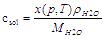 (5)
(5)
where x (p, T) - the fate of the molar solubility of gas in water; MH2O - molar mass of water, kg / mole (0.01802 kg / mole) ρH20- the density of water, kg/m3 .
According to the theory of diffusion, proportional to the concentration and without accumulation of gas mass transfer rate (rate of occurrence of gas hydrate) is calculated by the formula
r2 = kS Ac (cb – ceq), (6)
where r2 - speed gas hydrate occurrence, mol/s; kS - diffusion coefficient of gas from the liquid to the crystal hydrate, m/s; Ac - area of the crystal surface, m2; ceq-gas concentration in the liquid-crystal boundary at a pressure process and equilibrium temperature mol/m3 .
Considering that gas hydrate formation process depends on the diffusion of gas into the liquid and the surface of the crystal, one-component gas hydrate formation rate per 1 m3 of liquid is determined by the formula
r = k (ccol – ceq), (7)
where r - rate of hydrate formation, mole/m3c; k - coefficient of diffusion of gas bubbles to the surface of the crystal, 1/s.
Equation (7) describes the process of hydrate formation for one hydra creation gas. Furthermore, it ignores the volume and design features of the reactor hydrate.
Speed hydrate mixture of several hydra creation components is calculating by the formula [4]
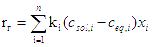 (8)
(8)
where rh - the rate of hydrate gas mixture mole/m3s, Ki - coefficient hydrate the i-th component of the gas mixture, l /s; n - the number of components of gas; xi - mole fate component in the gas mixture.
Rate of hydrate formation with hydrate based method and the volume of liquid in the reactor is calculated by the formula
 (9)
(9)
where R - the rate of hydrate formation, mole/s; kp - factor that depends on the particular reactor and found experimentally, 1/s, Vв - volume of fluid, which is formed hydrate, m3.
4. Conclusions
1. Production of gas hydrates is proposed to make ejection of gas and mixing the contents of the reactor free liquid jet with the introduction of raw gas in the bottom of the reactor and the derivation watergashydtrate mixture until it is clear phase separation resulting in agglomeration of gas hydrates.
2. Ejection of gas and mixing the contents of the reactor using a free jet will greatly streamline and simplify the design of the reactor. This circulation of fluid in the direction of jet apparatus - reactor - separator - heat exchanger - jet unit will simultaneously perform the ejection of gas, improve the quality of contact phase flow reactor in the required amount of water recharge, heat dissipation and output hydrate formed hydrates.
References
1. Zhong D.L., Liu D.P., Wu Z.M., Zhang L. Natural Gas Hydrate and Growth on Suspended Water Droplet. Proceeding of the 6th International Coference on Gas Hydrates (ICGH 2008), Vancouver, British Columbia, CANADA, July 6-10, 2008.
2. Gumerov N.A., G.L. Chahine Dynamics of bubbles in conditions of gas hydrate formations. Dynaflow Inc. Fulton, Maryland, USA, 1992. - С. 1 – 7.
3. Lara P. Onset of air entrainment for a water jet impinging vertically on a water surface. Chem. Eng. Sei. – 1979. - Vol. 34. - P. 1164-1165.
4. Skovborg P. A mass transport limited model for the growth of methane and ethane gas hydrates. ChemicalEngineeringScience. – 1994. – Vol.11. – P. 1131-1143.